1.What is Three-legged Boost Inductor?
The Three-legged inductor is a passive electronic component used to store and release electrical energy. The materials used for three-legged boost inductors are generally the same as those used for radial inductors. Whether it’s ferrite, iron powder, or other specialized magnetic materials, the core substance remains consistent across the board.
(★ If you want to learn more, please refer to this article: •Electronic Components: Introduction To The Principle Of Three-Pin Inductor)
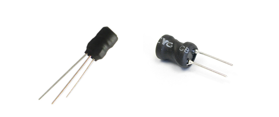
2.What is the difference between Three-legged Boost and radial inductor?
Typically, when referring to radial inductors, we mean a component with two pins and a single winding. On the other hand, three-legged boost inductors have three pins, which offer a high level of customization. The pins could be arranged in various configurations such as one long pin with two short ones, one short pin with two long ones, or a combination of long, medium, and short pins.
Once one pin is identified in a three-legged boost inductor, the other two are automatically determined, eliminating the need for special markings or identifiers. The three pins are in fixed positions, which can either follow a clockwise or counter-clockwise orientation on the pin map, and are immovable.
3.Methods for Differentiating the Pins of three-legged Boost inductors
When it comes to working with three-legged boost inductors, correctly identifying the function of each pin is crucial for effective circuit design and application. Here are some methods commonly used to differentiate the pins of these specialized inductors:
3.1: Utilizing a Multimeter for Pin Identification
A multimeter is a basic but effective instrument primarily used for measuring voltage, current, and resistance. For differentiating the pins of a three-legged boost inductor, the resistance measurement function of the multimeter is particularly useful. According to the boosting principle of three-legged boost inductors, they consist of a primary winding and a secondary winding. The primary winding has fewer turns and, consequently, lower resistance, while the secondary winding has more turns and higher resistance. The resistance values must satisfy the following condition: Total Winding Resistance (Combined) > Secondary Winding > Primary Winding. If a resistance measurement yields zero, it indicates a short-circuit; if the resistance reading is unstable or infinite, it signifies an open-circuit condition.
For example, if you have three pins labeled 1, 2, and 3, and upon testing you find:
– Resistance between 1-2: 40 ohms
– Resistance between 2-3: 442 ohms
– Resistance between 1-3: 570 ohms
Then, the pair 1-2 would be the primary winding and 2-3 would be the secondary winding. The highest resistance value (570 ohms) represents the combined resistance of both windings. In this case, pin 2 would be considered the “middle” pin.
3.2: Using an LCR Meter for More Precise Measurements
An LCR meter is a specialized instrument for measuring inductance (L), capacitance (C), and resistance (R). This method offers a simpler, quicker, and more accurate approach than using a multimeter for differentiating the pins of a three-legged boost inductor. Typically, the inductance measurement setting of the LCR meter is used for this purpose. Tests are conducted between two pins at a time.
For instance, if you measure the inductance between pins 1 and 2 and find it to be 636.4uH,
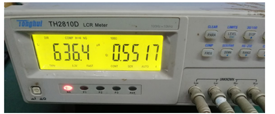
measure the inductance between pins 2 and 3 and find it to be 115.8uH,
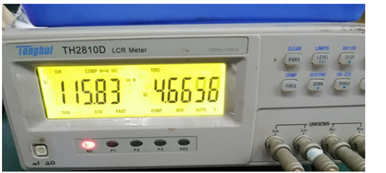
measure the inductance between pins 1 and 3 and find it to be 133.2uH,
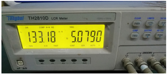
That means that the pair 1-2 represents the primary coil, while 2-3 is the secondary coil. The highest inductance value represents the combined inductance of both windings. In this case, pin 2 would be considered the “middle” pin.
The LCR meter method is generally the recommended approach for its superior accuracy and convenience in distinguishing between the primary and secondary windings of three-legged boost inductors.
3.3:Differentiation Using Pin length
Standardization by Length: For example, one long pin and two short pins; two long pins and one short pin; one long pin, one medium pin, and one short pin. Once one pin is distinguished, the other two are automatically defined. The best method for distinguishing between pins is to have one long pin and two short pins. The next best option is to have two long pins and one short pin. The least ideal method is to use three different lengths: long, medium, and short. Since the holes on the PCB are fixed, as are the pins, a white dot can be marked next to the common pin hole on the PCB as an indicator. For three-legged boost inductors, it’s recommended to use the “one long and two short pins” method, aligning the long pin with the white dot on the PCB.
3.4: Adding Additional marking on the three legged boost inductor’s Casing
In practice, the pins of a three-legged boost inductor are usually trimmed either before or after insertion. Once trimmed, the pins can no longer be distinguished by length alone. To solve this issue, a white stripe can be added to the inductor’s outer casing as an additional distinguishing feature.
The most efficient method for distinguishing the pins of a three-legged boost inductor is to use the longest pin as the “common” or “middle” pin. Additionally, a white stripe can be added to the casing at the location corresponding to the long pin as a distinguishing marker.
(★ If you want to know more information, check out more: • Electronic Smd Three-Pin Inductor Replaces Plug-In Three-Pin Inductor Application Case Sharing)
ZXcompo is a manufacturing company specializing in custom inductors, capacitors, resistors, and more. Find high-quality passive electronic components for your projects. If you have product needs and inquiries. Please contact us now: sales@ZXcompo.com


