The so-called inductor saturation actually means that when the magnetic core is saturated, the inductance value of the inductor element no longer increases linearly with the increase of current.
Under the action of saturation current, the inductance value of the inductor will no longer increase, but tend to a stable value, which is usually called saturation inductance value. So what are the factors that affect it?
Here we briefly talk about the influencing factors:
1. Magnetic permeability and saturation flux density of the magnetic core material
2. Magnetic core cross-sectional area
3. Number of turns
4. Magnetic core length
5. Inductor operating temperature
(★ If you want to know more, please refer to this article: •Inductor Saturation Current: The Key Factor In Inductor Selection)
Method for determining inductor saturation current: calculation method and test method
The first is the calculation method
1. According to the magnetic permeability and saturation flux density, cross-sectional area and number of turns of the magnetic core material, the Isat of the inductor can be calculated.
2. The changes in the material magnetic permeability and saturation flux density at the actual operating temperature must be considered during the calculation.
The second is the experimental method
1. Measure the inductance of the inductor and record the relationship curve between current I and inductance L.
2. Calculate Isat based on the inductance value and number of turns in the saturated state.
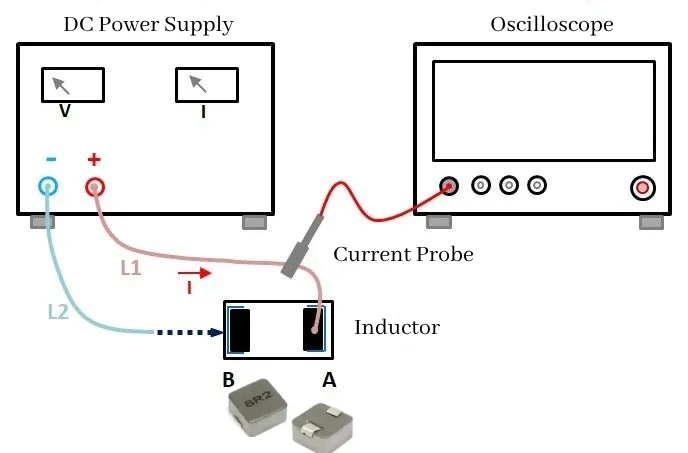
The steps to measure the inductor saturation current are as follows:
1. Use wire L1 to connect the positive end of the DC power supply to the A pin of the inductor, and weld the end of wire L1 to the A pin of the inductor.
2. Set the DC power supply output voltage to 10V and set the DC power supply current limit value. You can set a smaller value first, such as 1A.
3. Connect the current probe to the interface of the oscilloscope, and clamp the current probe bayonet end on wire L1. Pay attention to the direction of the current probe, which is consistent with the measured current direction.
4. Connect one end of wire L2 to the negative end of the DC power supply.
5. Set the oscilloscope to trigger the channel connected to the current probe, and set the trigger value to a smaller value, such as 0.2A; at the same time, the oscilloscope is set to single trigger.
6. Press the DC power supply output button to output DC voltage; hold the other end of wire L2 with your hand, let the wire head touch the B pin of the inductor, and then quickly remove wire L2 to disconnect the wire head from the B pin of the inductor.
7. Reduce the time base appropriately and observe the oscilloscope waveform. If the inductor current waveform becomes flat afterwards, increase the current limit value of the DC power supply and repeat steps 5 and 6 until the inductor current waveform shown in Figure 2 appears.
8. Measure the inflection point of the inductor current waveform. The inflection point is approximately the saturation current of the inductor. In Figure 2, the inflection point is approximately 13A, and the saturation current of the inductor is approximately 13A.
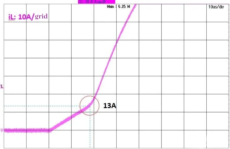
At the beginning, you can set the time base (X axis) and current scale (Y axis) larger, and then gradually reduce them to a suitable range according to the measured waveform to ensure that the complete current waveform can be seen.
When voltage is applied to both ends of the inductor, the inductor is magnetized, and the inductor current increases linearly with time:
L*dt/dt = V
When the inductor is saturated, L suddenly decreases sharply, the excitation voltage remains unchanged, and the inductor current change rate di/dt will increase sharply:
dt/dt = V/L
The inflection point where the inductor current change rate di/dt increases sharply is the saturation current of the inductor.
Advantages and disadvantages of calculation method and test method
The advantage of the calculation method is high accuracy, but it requires knowing the parameters of the core material, and it may be affected by factors such as operating temperature. The advantage of the test method is that the experiment is simple and easy to operate, but it requires the actual measurement of the inductor’s inductance value, which is not suitable for comprehensive detection of the inductor saturation current at the production site.
This article introduces in detail the concept and influencing factors of inductor saturation current, and proposes two methods to determine the inductor saturation current by calculation and experiment for reference by practitioners in related fields.
ZXcompo is a manufacturing company specializing in custom inductors, capacitors, resistors, and more. Find high-quality passive electronic components for your projects. If you have product needs and inquiries. Please contact us now: sales@ZXcompo.com