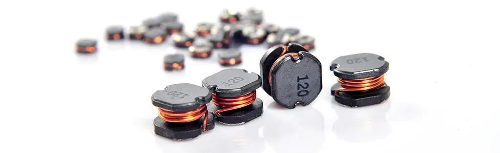
Common Mode Choke Principle
Common mode choke is an electronic component whose main function is to provide suppression for common mode interference in the circuit. Ideally, it is designed to isolate the same polarity current between L (or N) and E, that is, the common mode current, and will not produce inductive suppression for the different polarity current between L and N, that is, the differential mode current. However, the actual common mode choke may have the problem of incomplete winding symmetry, which will lead to the generation of differential mode leakage inductance.
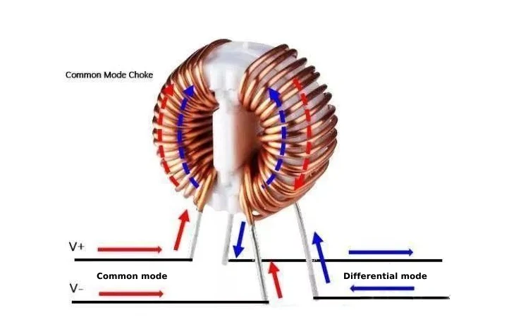
When the signal current or power current flows in opposite directions in the two windings, the magnetic flux they generate will cancel each other, making the common mode choke exhibit low impedance characteristics. In this case, the circuit is relatively smooth for the transmission of signal current. However, the common mode noise current, including the disturbance current caused by the ground loop, will generate the same direction of magnetic flux in the two windings because its current direction is the same as the signal current.
The superposition of this unidirectional magnetic flux makes the common mode choke present high impedance, thereby effectively suppressing the propagation of common mode noise and realizing the common mode noise protection of the circuit
In electronic equipment, especially in equipment involving electromagnetic fields, the role of common mode inductors and common mode chokes is crucial. The main function of common mode inductors and common mode chokes is to filter out interference signals on the power line to ensure the stability of the power supply. In this article, we will explore how to correctly select common mode chokes and the application of common mode chokes.
Common Mode Choke Selection Points
Several factors need to be considered when selecting a common mode inductive choke to ensure that it can effectively suppress common mode interference in a specific application.
Here are some key selection considerations:
1. Frequency range:
Determine the frequency range of the interference signal that needs to be suppressed. Common mode inductors have different impedance characteristics at different frequencies, so it is necessary to select an inductance value that can provide sufficient impedance in the target frequency range.
2. Inductance value:
Choose the appropriate inductance value based on the common mode current of the circuit and the desired suppression effect. Generally, the larger the inductance value, the stronger the suppression ability of high frequency interference.
3. Saturation current:
Make sure that the saturation current of the selected common mode inductor is greater than the maximum common mode current in the circuit to avoid the inductor entering the saturation state and losing the ability to suppress interference.
4. Insertion loss:
Insertion loss refers to the degree of attenuation of the common mode inductor to the interference signal. Selecting a common mode inductor with a higher insertion loss can greatly attenuate the interference signal before it enters the circuit.
5. DC resistance (DCR):
DC resistance affects the power loss of the common mode inductor. For power-sensitive applications, a common-mode inductor with a lower DCR should be selected.
6. Package size:
Choose an appropriate package size based on the board space and design requirements. Make sure that the selected inductor can physically fit the board design.
7. Temperature range:
Consider the temperature range in the application environment and select a common-mode inductor that can work stably within this temperature range.
8. Shielding effect:
For some high-interference environments, it may be necessary to select a common-mode inductor with a shielding structure to provide additional interference suppression capabilities.
9. Cost:
Choose an appropriate common-mode inductor based on the budget and cost requirements of the project. The cost of inductors of different brands and models may vary significantly.
10. Certification and standards:
Make sure that the selected common-mode inductor meets relevant industry standards and certification requirements, such as CE, FCC, UL, etc.
When making a selection, you can refer to the specifications and data sheets provided by the inductor manufacturer for detailed comparison. In addition, actual testing and simulation are also effective methods to determine the best common-mode inductor selection.
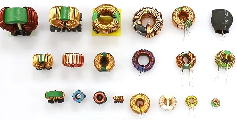
Difference Between Common Mode Inductor and Common Mode Choke
1. Structural difference
Common mode inductor and common mode choke are slightly different in structure. Common mode inductor is usually composed of two magnetic materials, with the center line passing through the sun, and two coils are wound separately. Common mode choke is to wind the two coils tightly together, like an X-shaped arrangement that crosses each other.
2. Difference in working principle
The working principle of common mode inductor and common mode choke is also different. Common mode inductor uses the effect of self-inductance and mutual inductance to suppress electromagnetic interference signals, so it is very suitable as an attenuator in power supply filter and signal processing circuit. Common mode choke uses magnetic coupling effect to achieve the purpose of suppressing electromagnetic interference, so it is more suitable for use in transmission lines and data communications.
3. Difference in application field
Due to the different working principles of the two, common mode inductor and common mode choke are also different in application. Common mode inductor can be used in many devices and circuits, such as power amplifiers, computer internal hard disk drives, etc., which can effectively filter DC and low-frequency electromagnetic noise.
Common-mode chokes are often used in the field of data transmission, such as audio equipment, modems, and telephone lines. Because data transmission requires high-speed transmission, many high-frequency interference signals will also be transmitted. Common-mode chokes can effectively offset these interference signals and ensure the quality of data transmission.
4. Differences in material selection
The material selection of common-mode inductors and common-mode chokes varies according to specific application requirements. The most commonly used material for common-mode inductors is ferrite, while common-mode chokes can be made of various conductive materials, such as copper wire, aluminum wire, etc. The choice of materials will also affect the impedance values of the two.
In summary, common-mode inductors and common-mode chokes are both electromagnetic interference suppression components, but the two are different in structure, working principle, application field, and material selection. Correctly selecting the right components can more effectively suppress electromagnetic interference and improve the reliability and stability of equipment.
Common Mode Choke Application
Common mode choke is mainly used to filter common mode electromagnetic interference signals. It plays an important role in electronic circuits, especially in computer switching power supplies, used to suppress the electromagnetic waves generated by high-speed signal lines from radiating outward. Common mode choke has a certain common mode interference attenuation capability through its characteristics, thereby effectively reducing the impact of electromagnetic interference on the circuit.
The application scenarios of common mode chokes are very wide, including but not limited to:
1. Switching power supply noise suppression filter:
In switching power supplies, common mode chokes are used to filter and reduce common mode electromagnetic interference generated by power switch operation to ensure stable output of power supply and normal operation of equipment.
2. Power line and signal line electrostatic noise filter:
In the application of power line and signal line, common mode chokes can effectively reduce electrostatic noise and protect electronic equipment from electrostatic interference.
3. Radiated interference suppressor such as converters and ultrasonic equipment:
For equipment that requires high electromagnetic compatibility, such as converters and ultrasonic equipment, common mode chokes are used to suppress radiated interference to ensure the normal operation of the equipment and clear transmission of signals.
4. Automotive electronics:
In automotive electronics systems, common mode chokes are used to enhance electromagnetic compatibility, especially in safety-critical applications such as controller area network (CAN) or FlexRav systems, where common mode chokes can enhance protection against faults caused by electromagnetic compatibility issues.
5. High-definition multimedia interface signal quality maintenance:
In applications such as high-definition multimedia interface (HDMI), common mode chokes are used to maintain signal quality, ensuring clear signal transmission and normal operation of the device.
6. Impedance matching:
Common mode chokes are also used for impedance matching to ensure that the transmitted signal has no radiation and meets specific electromagnetic compatibility standards.
(★ If you want to know more information, you can refer to the following article: •What Are The Functions Of Common Mode Inductors In Circuits?)
In summary, the selection of common mode inductors and common mode chokes needs to take into account multiple factors, including impedance, current, core material, coil material and wire diameter, packaging and heat dissipation performance. In practical applications, common mode chokes play a vital role in electronic devices, whether in terms of improving device performance, ensuring the stability of data transmission, or improving the electromagnetic compatibility of the device. It is necessary to select and design according to the actual needs of the device to ensure the stability and reliability of the power supply. At the same time, it is also necessary to pay attention to the power architecture and cost constraints of the equipment to select the most suitable solution.